OXYGEN SENSOR BYPASS CIRCUIT
Sat, 31 May 2008 17:55:07
By PCIDPUSA,
SENSOR BYPASS CIRCUIT
Electrical diagram
How to build Your Own Oxygen
Sensor Simulator!
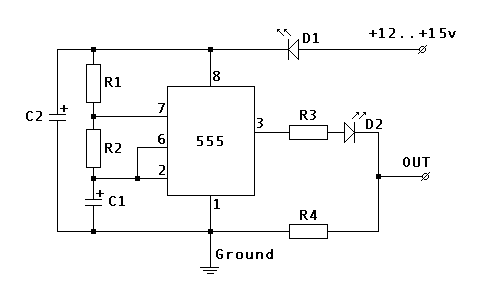
The rest of the page shows how to build an oscillating signal generator with
just the right frequency and voltage to fool the ECU. It is based on classical
astable operating mode of 555 timer, so nothing revolutionary there. However we
spent few days of fiddling and testing to get the right behavior.
The parts will cost about $15 – $20 from RadioShack. It’s not that hard to
build if you have some experience.
Components:
| R1 | 100 K Ohm |
| 1 M Ohm | |
| R3 | 100 K Ohm |
| R4 | 10 K Ohm |
| C1 | 4.7 uF |
| C2 | 22 uF |
| D1 | 1.7v@20mA LED |
| D2 | 1.7v@20mA LED |
Hookup:
| Power source | Ignition, or to the |
| Ground | One of the ground points or |
| OUT | (disconnect the O2 sensor wire) |
Catalog part numbers from RadioShack stores:
(NOT for their online
system)
| 276-309 | 5mm wide angle red led 1.7v, 20mA |
| 276-1723 | The 555 programmable timer |
| 276-1995A | The 8 pin socket for timer chip. It makes soldering safer and replacement easier |
| 276-150A | Generic PC board |
| 64-3052A | Pack of blue tap-in connectors |
| 278-1225 | Stranded wires (black, red and green) |
| 270-1801 | Small black plastic project box 3 x 2 x 1 |
| 272-1024 | Capacitor, 4.7uF |
| 272-1026 | Capacitor, 22uF |
Additional notes:
If you use different flavors of 555 timer chip or LEDs with different
parameters you will need to readjust the values of R4 and R2 to get the interval
and output voltage right.
Don’t attach it directly to the ECU right after assembly. Instead attach it
to the battery and check the output. You should get approximately 0v/0.7v
flipping about every 3.3 seconds when the car is not running, and 0v/0.9v when
the car is running. The current should stay below 10mA.
One LED should be always on whenever the power is supplied. Another LED
indicates when the output signal is high, so it should go on and off with the
signal.
When tapping the ECU wires, triple check everything before hooking up the
oscillator. The power source should read 0v when the key is removed, about 12.6v
when they key is at ACC and about 14.3 when the alternator is running. The
resistance between ground wire and the body shield of the ECU should be 0 ohms.
And it would be best if you run the car and monitor the voltage of the original
oxygen sensor wire before cutting it to make sure you have indeed got the right
one. The resistance between and ground is about 1.3 to 1.6 M Ohm.
The original sensor should still be dangling around, or plugged into the
downpipe. The reason is that ECU also monitors the resistance of heater circuit
inside the sensor. If you want to COMPELTELY disconnect it, you will need to
measure the resistance of the heater circuit and install the right resistor
Anyway, there is no need to do it if you just leave O2 sensor alone and
only intercept the oxygen signal wire.
Above testing and precautions will prevent you from frying the ECU and
spending major $$$$. Anyway, I assume no responsibility if you still manage todo so.
Autoimmune Diseases Treatment
Electrical Stimulation Therapy
magnets and ageing
Sand Bath for health
Glutathione super supplement
= Sulphur Bath for Detox and health
Massage Cancer Cure
Water chestnut amazing nutrition
Infants women omega-3 for healthy baby
Selenium the specialfood
Capsaicin
North American Herbs
Small fiber neuropathy
Gout Garlic
Magnetic deficiency
Pathology
Variants
CIDP
info
Fibromyalgia
IVIG
Diet
Burning Feet Home
Services Page
Chronic Fatigue
Autoimmune diseases
Prognosis
Bible healing
Celiac disease